- 您现在的位置:买卖IC网 > Sheet目录868 > LSN2-T/30-D12-C (Murata Power Solutions Inc)CONV DC/DC 150W 30A 0.8-5V SIP
�� �
�
�LSN2-T/30-D12� Series�
�DOSA-SIP,� 30A� POL� DC/DC� Converters�
�Performance/Functional� Speci?cation� Notes:�
�(1)� Speci?cations� are� typical� at� +25°C,� V� IN� =� nominal� (+12V),� V� OUT� =� nominal� (+5V),� full�
�load,� external� caps� and� natural� convection� unless� otherwise� indicated.�
�All� models� are� tested� and� speci?ed� with� external� 0.01μF,� 0.1μF,� and� 10μF� (all� paral-�
�leled)� ceramic/tantalum� output� capacitors� and� a� 22μF� external� input� capacitor.� All�
�capacitors� are� low� ESR� types.� These� capacitors� are� necessary� to� accommodate� our�
�test� equipment� and� may� not� be� required� to� achieve� speci?ed� performance� in� your�
�applications.� All� models� are� stable� and� regulate� within� spec� under� no-load� conditions.�
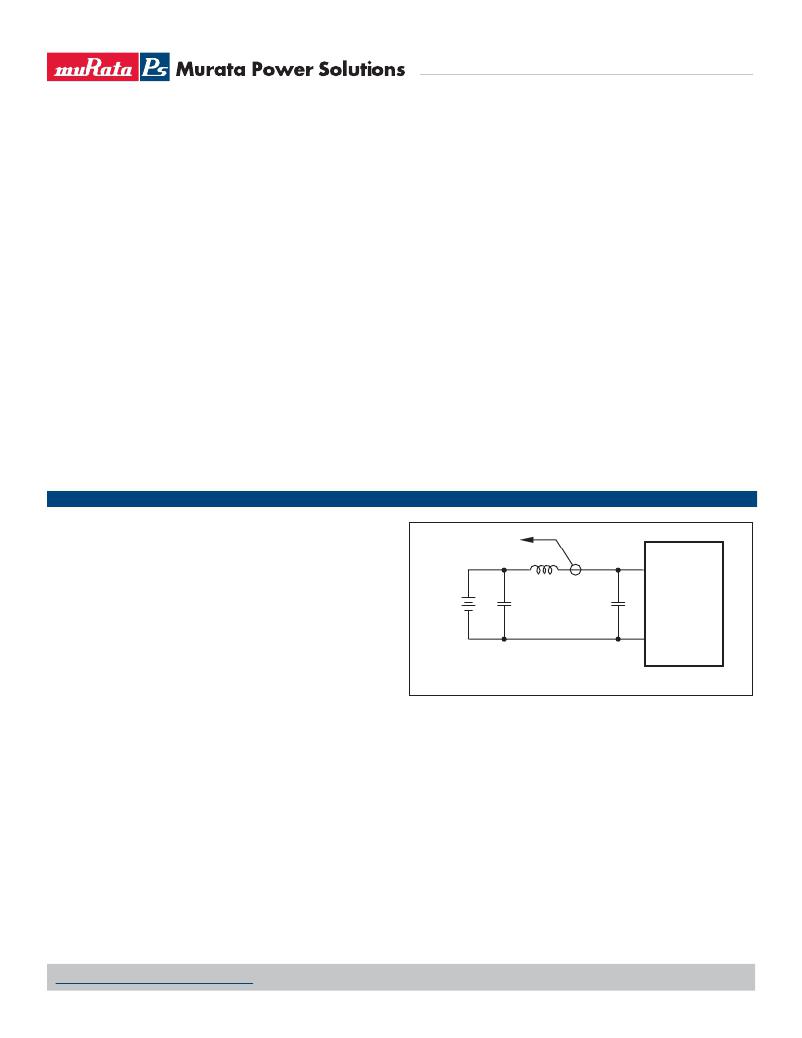
�(2)� Input� Back� Ripple� Current� is� tested� and� speci?ed� over� a� 5Hz� to� 20MHz� bandwidth.�
�Input� ?ltering� is� C� IN� =� 2� x� 100μF� tantalum,� C� BUS� =� 1000μF� electrolytic,� L� BUS� =� 1μH.�
�(3)� Note� that� Maximum� Power� Derating� curves� indicate� an� average� current� at� nominal�
�input� voltage.� At� higher� temperatures� and/or� lower� air?ow,� the� DC/DC� converter� will�
�tolerate� brief� full� current� outputs� if� the� total� RMS� current� over� time� does� not� exceed� the�
�Derating� curve.�
�(4)� Mean� Time� Before� Failure� is� calculated� using� the� Telcordia� (Belcore)� SR-332�
�Method� 1,� Case� 3,� ground� ?xed� conditions,� TPCBOARD� =� +25°C,� full� output� load,�
�natural� air� convection.�
�(5)� The� On/Off� Control� may� be� driven� with� external� logic� or� by� applying� appropriate� exter-�
�nal� voltages� which� are� referenced� to� –Input� Common.� The� On/Off� Control� Input� should�
�use� either� an� open� collector/open� drain� transistor� or� logic� gate.�
�(6)� Short� circuit� shutdown� begins� when� the� output� voltage� degrades� approximately� 2%�
�from� the� selected� setting.�
�(7)� If� Sense� is� connected� remotely� at� the� load,� up� to� 0.5� Volts� difference� is� allowed� between�
�(8)� Output� noise� may� be� further� reduced� by� adding� an� external� ?lter.� See� I/O� Filtering� and�
�Noise� Reduction.�
�(9)� All� models� are� fully� operational� and� meet� published� speci?cations,� including� “cold� start”�
�at� –40°C.�
�(10)� Regulation� speci?cations� describe� the� deviation� as� the� line� input� voltage� or� output� load�
�current� is� varied� from� a� nominal� midpoint� value� to� either� extreme.�
�(11)� Other� input� or� output� voltage� ranges� will� be� reviewed� under� scheduled� quantity� special�
�order.�
�(12)� Maximum� PC� board� temperature� is� measured� with� the� sensor� in� the� center.�
�(13)� Do� not� exceed� maximum� power� speci?cations� when� adjusting� the� output� trim.�
�(14)� After� short� circuit� shutdown,� if� the� load� is� partially� removed� such� that� the� load� still�
�exceeds� the� overcurrent� (OC)� detection,� the� converter� will� remain� in� hiccup� restart� mode.�
�(15)� Static� Discharge� CAUTION:� The� Power� Good� output� connects� directly� to� the� PWM�
�controller.� Be� sure� to� use� proper� grounding� techniques� to� avoid� damaging� the� converter.�
�Power� Good� is� not� valid� when� using� Sequence/Tracking.�
�(16)� The� maximum� output� capacitive� loads� depend� on� the� the� Equivalent� Series� Resistance�
�(ESR)� of� theexternal� output� capacitor.� Larger� caps� will� reduce� output� noise� but� may�
�slow� transient� response� or� degrade� dynamic� performance.� Use� only� as� much� output� ?l-�
�tering� as� needed� and� no� more� .� Thoroughly� test� your� system� under� full� load,� especially�
�with� low-ESR� ceramic� capacitors.�
�(17)� Do� not� use� Pre-bias� startup� and� sequencing� together.� See� the� Technical� Notes� below.�
�the� Sense� and� +V� OUT� pins� to� compensate� for� ohmic� voltage� drop� in� the� power� lines.�
�A� larger� voltage� drop� may� cause� the� converter� to� exceed� maximum� power� dissipation.�
�Connect� sense� to� +V� OUT� at� the� converter� if� sense� is� not� connected� to� a� remote� load.�
�TECHNICAL� NOTES�
�I/O� Filtering� and� Noise� Reduction�
�All� models� in� the� LSN2-T/30-D12� Series� are� tested� and� speci?ed� with� external�
�0.01μF,� 0.1μF,� and� 10μF� (all� paralleled)� ceramic/tantalum� output� capaci-�
�tors� and� a� 22μF� tantalum� input� capacitor.� These� capacitors� are� necessary� to�
�accommodate� our� test� equipment� and� may� not� be� required� to� achieve� desired�
�performance� in� your� application.� The� LSN2-T/30-D12’s� are� designed� with�
�high-quality,� high-performance� internal� I/O� caps,� and� will� operate� within� spec�
�in� most� applications� with� no� additional� external� components.�
�In� particular,� the� LSN2-T/30-D12’s� input� capacitors� are� speci?ed� for� low�
�ESR� and� are� fully� rated� to� handle� the� units’� input� ripple� currents.� Similarly,� the�
�internal� output� capacitors� are� speci?ed� for� low� ESR� and� full-range� frequency�
�response.�
�Figure� 2.� Measuring� Input� Ripple� Current�
�In� critical� applications,� input/output� ripple/noise� may� be� further� reduced� using�
�?ltering� techniques,� the� simplest� being� the� installation� of� external� I/O� caps.�
�External� input� capacitors� serve� primarily� as� energy-storage� devices.� They�
�minimize� high-frequency� variations� in� input� voltage� (usually� caused� by� IR� drops�
�in� conductors� leading� to� the� DC/DC)� as� the� switching� converter� draws� pulses� of�
�current.� Input� capacitors� should� be� selected� for� bulk� capacitance� (at� appropri-�
�ate� frequencies),� low� ESR,� and� high� rms-ripple-current� ratings.� The� switching�
�nature� of� modern� DC/DCs� requires� that� the� dc� input� voltage� source� have� low� ac�
�impedance� at� the� frequencies� of� interest.� Highly� inductive� source� impedances�
�can� greatly� affect� system� stability.� Your� speci?c� system� con?guration� may�
�Output� ripple/noise� (also� referred� to� as� periodic� and� random� deviations� or�
�PARD)� may� be� reduced� below� speci?ed� limits� with� the� installation� of� additional�
�external� output� capacitors.� Output� capacitors� function� as� true� ?lter� elements�
�and� should� be� selected� for� bulk� capacitance,� low� ESR,� and� appropriate� fre-�
�quency� response.� Any� scope� measurements� of� PARD� should� be� made� directly�
�at� the� DC/DC� output� pins� with� scope� probe� ground� less� than� 0.5"� in� length.�
�All� external� capacitors� should� have� appropriate� voltage� ratings� and� be� located�
�as� close� to� the� converters� as� possible.� Temperature� variations� for� all� relevant�
�parameters� should� be� taken� into� consideration.�
�necessitate� additional� considerations.�
�www.murata-ps.com/support�
�MDC_LSN2-T/30-D12� Series.C01� Δ� Page� 5� of� 16�
�发布紧急采购,3分钟左右您将得到回复。
相关PDF资料
LSS-T/10-W12-C
CONV DC/DC 60W 10A .6-6V SIP
LTM4600HVIV#PBF
IC DC/DC UMODULE 10A 104-LGA
LTM4600IV#PBF
IC DC/DC UMODULE 10A 104-LGA
LTM4601AHVEV#PBF
IC DC/DC UMODULE 12A 133-LGA
LTM4601AIY#PBF
IC DC/DC UMODULE 12A 133-BGA
LTM4602IV#PBF
IC DC/DC UMODULE 6A 104-LGA
LTM4603HVEV#PBF
IC DC/DC UMODULE 6A 118-LGA
LTM4603IV#PBF
IC DC/DC UMODULE 6A 118-LGA
相关代理商/技术参数
LSN2-T/30-D12G-C
功能描述:DC/DC转换器 12Vin 0.8-5Vout 30A 150W Power Good Out
RoHS:否 制造商:Murata 产品: 输出功率: 输入电压范围:3.6 V to 5.5 V 输入电压(标称): 输出端数量:1 输出电压(通道 1):3.3 V 输出电流(通道 1):600 mA 输出电压(通道 2): 输出电流(通道 2): 安装风格:SMD/SMT 封装 / 箱体尺寸:
LSN2-T/30-D12N-C
功能描述:DC/DC转换器 12Vin 0.8-5Vout 30A 150W Neg polarity RoHS:否 制造商:Murata 产品: 输出功率: 输入电压范围:3.6 V to 5.5 V 输入电压(标称): 输出端数量:1 输出电压(通道 1):3.3 V 输出电流(通道 1):600 mA 输出电压(通道 2): 输出电流(通道 2): 安装风格:SMD/SMT 封装 / 箱体尺寸:
LSN2-T/30-D12NG-C
功能描述:DC/DC转换器 12Vin 0.8-5Vout 30A 150W PowerGood NegPl RoHS:否 制造商:Murata 产品: 输出功率: 输入电压范围:3.6 V to 5.5 V 输入电压(标称): 输出端数量:1 输出电压(通道 1):3.3 V 输出电流(通道 1):600 mA 输出电压(通道 2): 输出电流(通道 2): 安装风格:SMD/SMT 封装 / 箱体尺寸:
LSN2-T/6-C
制造商:CANDD 制造商全称:C&D Technologies 功能描述:Non-isolated, DOSA-SIP, 6/10/16A Selectable-Output DC/DC Converters
LSN2-T/6-D12
制造商:CANDD 制造商全称:C&D Technologies 功能描述:Non-isolated, DOSA-SIP, 6/10/16A Selectable-Output DC/DC Converters
LSN2-T/6-D12-C
功能描述:DC/DC转换器 19.8W 12V/0.75-5V 6A RoHS:否 制造商:Murata 产品: 输出功率: 输入电压范围:3.6 V to 5.5 V 输入电压(标称): 输出端数量:1 输出电压(通道 1):3.3 V 输出电流(通道 1):600 mA 输出电压(通道 2): 输出电流(通道 2): 安装风格:SMD/SMT 封装 / 箱体尺寸:
LSN2-T/6-D12G-C
功能描述:DC/DC转换器 19.8W 12V/0.75-5V 6A RoHS:否 制造商:Murata 产品: 输出功率: 输入电压范围:3.6 V to 5.5 V 输入电压(标称): 输出端数量:1 输出电压(通道 1):3.3 V 输出电流(通道 1):600 mA 输出电压(通道 2): 输出电流(通道 2): 安装风格:SMD/SMT 封装 / 箱体尺寸:
LSN2-T/6-D12N-C
功能描述:DC/DC转换器 19.8W 12V/0.75-5V 6A
RoHS:否 制造商:Murata 产品: 输出功率: 输入电压范围:3.6 V to 5.5 V 输入电压(标称): 输出端数量:1 输出电压(通道 1):3.3 V 输出电流(通道 1):600 mA 输出电压(通道 2): 输出电流(通道 2): 安装风格:SMD/SMT 封装 / 箱体尺寸: